IBA Module
An Integrated Blumlein Antenna Array
PCSS-Based High-Power Microwave System
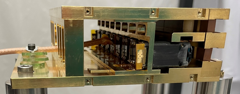
Figure 1. A Single IBA Module
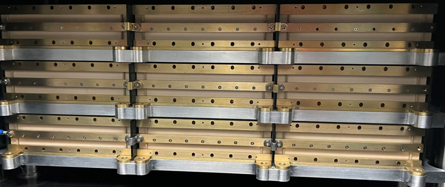
Figure 2. A 3x3 IBA Array
Eureka Aerospace’s design efforts are primarily focused on the development of a compact and mobile Photoconductive Semiconductor Switch (PCSS)-based High-Power Microwave System (HPMS). We utilize multiple PCSS Assemblies to achieve system modularity and scalability. The PCSS Assemblies are simultaneously triggered with miniature Laser Diode Array (LDA) chips.
Our flagship "Integrated Blumlein Antenna (IBA) Module" (Figure 1) integrates eight PCSS assemblies into one module measuring only 5” x 4” x 1”. The module acts as both a microwave source and a radiator, and is tunable within the 100 MHz to 1 GHz frequency range. No external antenna is needed. Depending on the operational requirements, the IBA module is scalable to any size.
The IBA modules can also be further extended for greater power, modularity and scalability as exemplified by our 3x3 IBA Array (Figure 2). The modules are integrated into a rectangular-shaped structure called the Integrated Blumlein Antenna (IBA) Array. The larger the standoff, the more modules are integrated into the IBA Array.
IBA Module and Array Output
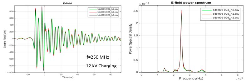
Figures below are illustrative examples of the output Radiated Field at 1 meter away from source and the corresponding Power Spectrum from a single Integrated Blumlein Antenna (IBA) Module, a 3 x1 IBA Module Array, as well as a 3 x 3 IBA Module Array.
The left image of Figure 1 shows the output electric field over time from a single IBA module, measured at 1 meter distance in front, as it gets energized. The right image shows the corresponding power spectrum, which indicates a clear concentration of power at a set frequency.

Figure 1. Radiated field and power spectrum output of a single IBA module
Figure 2 shows the E-field output and it's power spectrum from both a 3 x1 IBA module array (green) and a 3 x 3 IBA module array (red). Both radiate a concentrated energy at the same targeted frequency, but with a much higher power density for the 3 x 3 module array, more than 3 times than for the 3 x 1 module array.
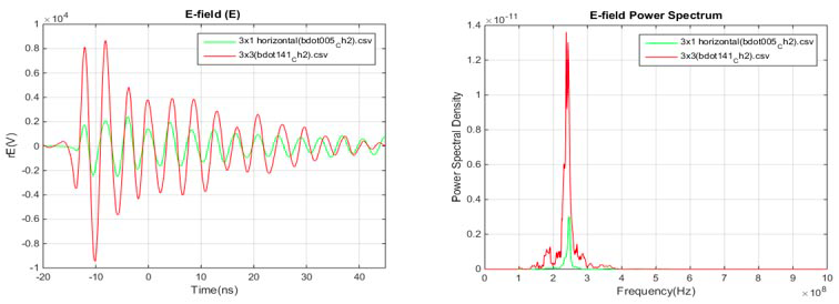
Figure 2. Radiated field and power spectrum output of both a single IBA module and a 3x3 IBA module array
Figure 3 shows the E-field output and it's power spectrum from three separate individual IBA modules (green, red and blue). We see that the outputs are near identical for all three modules, thus demonstrating the modularity of the IBA systems.
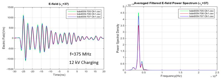
Figure 3. Radiated field and power spectrum output of three individual IBA modules
Figure 4, like Figure 3, shows the E-field output and it's power spectrum from three separate individual IBA modules (green, red and blue). However, we see a concentrated power at a different frequency, 250 MHz instead of 375 MHz from Figure 3, thus demonstrating the frequency tunability of the IBA system.
